Overview & Designation Matrix
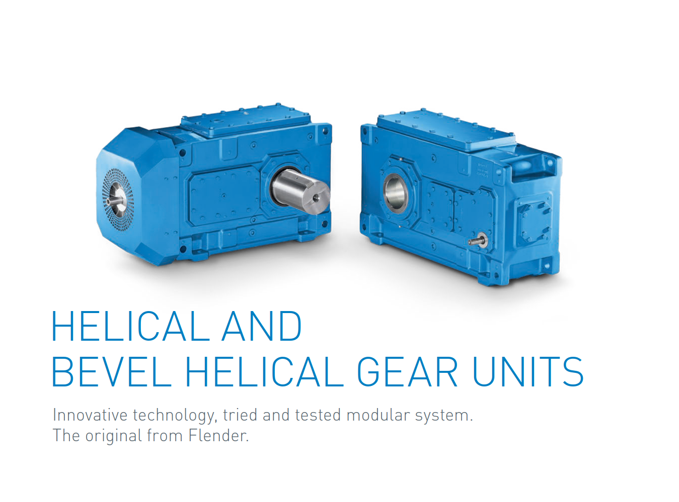
Explore heavy-duty engineering designs and modular options for FLENDER® Helical H Series & Bevel-Helical B Series gear units. Full technical interchangeability supported by WeDrive Power Transmission.
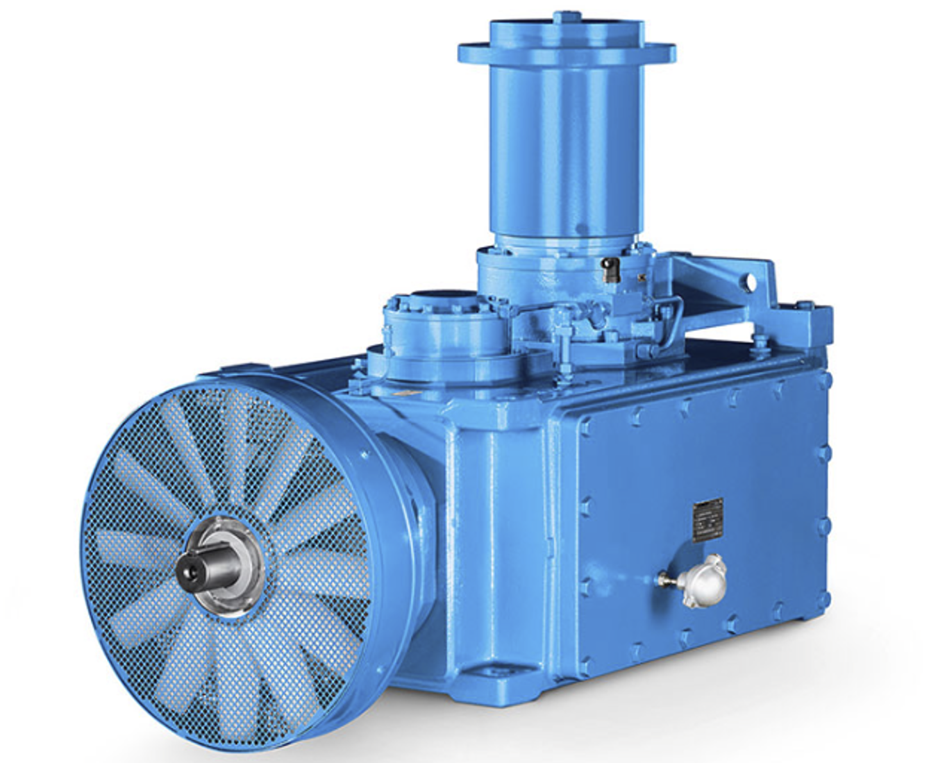
Target Industries & Field Applications

Our heavy-duty FLENDER Industrial Gear Units are engineered specifically for severe operational environments. This versatile, time-tested design delivers exceptional reliability across continuous process applications, running seamlessly from high-torque mineral crushing to precision port lifting machinery.

The engineering data above outlines the standard dimensions for FLENDER gearboxes. It provides crucial sizing benchmarks covering specific torque outputs and ratio selections across various casing footprints.
FLENDER DESIGNS AND SIZES - Technical Specifications
| Gear Unit Type | Nominal Torque Class T2N (Nm) | Ratio Range (i) |
|---|---|---|
| Helical Gear Unit H1 | 3,300 - 75,700 Nm | 1.25 - 5.6 |
| Helical Gear Unit H2 | 3,500 - 107,000 Nm | 6.3 - 28 |
| Helical Gear Unit H3 | 11,600 - 109,000 Nm | 22.4 - 112 |
| Helical Gear Unit H4 | 21,700 - 113,000 Nm | 100 - 450 |
| Bevel-helical B2 | 6,200 - 101,000 Nm | 5 - 22.4 |
| Bevel-helical B3 | 3,600 - 113,000 Nm | 12.5 - 90 |
| Bevel-helical B4 | 11,600 - 113,000 Nm | 80 - 400 |
* Note: Nominal torque and ratio ranges are based on standard FLENDER industrial configurations.

The chart below exhibits the maximum torque capacities for multi-stage gear transmission setups. For customized thermal capacities or special forced lubrication options, consult WeDrive engineering teams directly.
| Type | Size Range | Nominal Torque T2N (Nm) | Ratio Range (i) |
|---|---|---|---|
| H1.. (Single-stage) | 03 - 19 | 3,300 - 245,000 Nm | 1.25 - 5.6 |
| H2.. (Two-stage) | 03 - 28 | 3,500 - 1,400,000 Nm | 6.3 - 28 |
| H3.. (Three-stage) | 05 - 28 | 11,600 - 1,400,000 Nm | 22.4 - 112 |
| H4.. (Four-stage) | 07 - 28 | 21,700 - 1,400,000 Nm | 100 - 450 |
| B2.. (Two-stage) | 04 - 18 | 6,200 - 230,000 Nm | 5 - 22.4 |
| B3.. (Three-stage) | 03 - 28 | 3,600 - 1,400,000 Nm | 12.5 - 90 |
| B4.. (Four-stage) | 05 - 28 | 11,600 - 1,400,000 Nm | 80 - 400 |

Understanding the exact nomenclature parameters ensures perfect fitments during part number replication or plant replacement procurement cycles.
Structure of Gear Unit Designation (Example: B3SH11A16)
- B: Bevel-helical gear units
- 3: No. of stages (3 stages)
- S: Solid shaft with parallel key
- H: Horizontal mounting position
- 11: Gear unit size identifier
- A: Structural Version A
- 16: Nominal Ratio i = 16

Above detailed configuration covers specialized high-ratio co-axial drives. WeDrive offers full interchangeability components matching genuine industrial footprint profiles accurately.

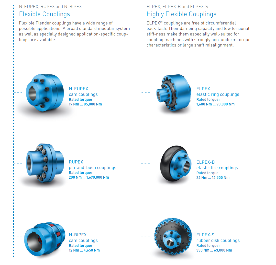
Detailed transmission limits for FLENDER flexible shaft couplings. Proper coupling configuration eliminates shaft misalignment stresses and cushions severe shock loads within driving linkages.

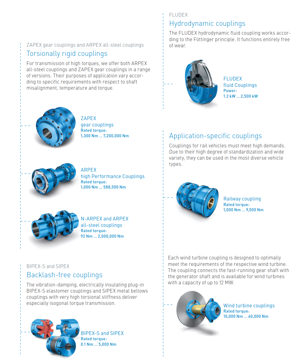
The structural matrix above illustrates technical boundaries for heavy-duty all-steel disc couplings, ensuring premium backlash-free torque consistency across synchronous operating systems.

Overview of hydrodynamic fluid coupling variables. Ideal for soft-starting high-inertia industrial conveyors and preventing unexpected overload torque breaks.
FLENDER Couplings - Product Series Overview
| Category | Series / Model Name |
|---|---|
| Torsionally Rigid Gear Couplings | ZAPEX ZW / ZAPEX ZN |
| Torsionally Rigid All-Steel Couplings | N-ARPEX, ARPEX |
| Flexible Couplings | N-EUPEX / RUPEX / N-BIPEX |
| Highly Flexible Couplings | ELPEX-B / ELPEX-S / ELPEX |
| Fluid Couplings | FLUDEX |
| Backlash-free Couplings | SIPEX / BIPEX-S |
* WeDrive provides full technical support for FLENDER power transmission components. Our selection includes both torsionally rigid and highly flexible options for diverse industrial applications.